تصميم الجيد للجوارب هي بداية جيدة لاي تنافسية في سوق الجوارب فإضافة الى نوعية القطن المستعمل في صناعة الجوارب واتقان العمل يعتبر التصميم من المحددات الاساسية لقيمة المنتوج
هنا في هذا الموقع سنتعلم كيفية تصميم الجوارب بشكل جيد وسنستعلم برنامج ROSSO SOCK وهو برنامج يتشابه مع البرامج الاخرى وهذا حسب طبيعة الالة المستعلمة نحن نستعمل الة ROSSO
يمكنك طرح سؤالك في التعليق وسنعمل على حل مشكلتك
اولا لنتعرف على البرنامج
واجهة البرنامج

Cotton Sock Designer Manual V1.0
Zhejiang Mind Robotization & Equipment Co., Ltd.
July, 1st, 2014
Catalogue
1 Introduction
Thank you for choosing our production. Before you install and use this software, ensure you have read this manual carefully, the manual will help you to master how to install and use the cotton sock designer software.
The cotton sock designer software is developed and tested by software team of Zhejiang Mind Robotization & Equipment Co., Ltd. This software is developed for assiting Sock Knitting Machine Control System, which has the function of automatic programing. It can generate a file with controling data for sock knitting machine control system. The functions of sock designer software contains pattern design, chain edit, machine parameters setting, data transmission and so on.
2 Hardware requirement
OS: Windows XP/Vista/Win7 English system
Clock Speed: Intel Pentium 2G Hz or AMD Anthon 2G Hz above.
Memory: Above 1GB(2GB is recommended).
Disk: Above 256MB.
Display: 17 inches(resolution by 1280*800 is recommended).
Other: Has USB interface in PC.
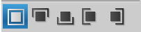
3 Interface style
This software designed in Microsoft OS, so the windows, dialogs and other visible components in the software are similar with what we use in Microsoft OS. Pull-down menu, pop-up menu, toolbar menu, main workspace and prompt dialog make the operation convenient and easy. See figure 3.1.
الواجهة تحتوي على مجموعة من الاوامر مع مساحة العمل المخططة وهي تمثل الجورب كل مربع صغير عبارة عن ابرة لهذا عرض المساحة 168 مربع بعدد الابر 168 ابرة

Figure 3.1 Main interface
4 Main function modules
4.1 Installation steps
When your PC is connecting with internet, input the website of “http://www.hzmind.com” in your browser, then you can download the software in the web. After download the RAR file, you can extract it to some folder in your PC, see figure 4.1.
Click the file “MindCottonSocks.exe” to run the software.
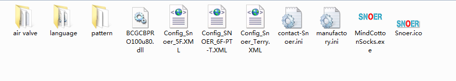
Figure 4.1 The software folder after extract the RAR file
4.2 Summary of painting designing
Click the pull-down menu and its submenu, icons of toolbar, this operation is good for pattern design. There are some units we need in paiting the pattern: point, line, rectangle, oval, diamond and polygon. The software’s functions are like below: fill color, text input, color picker, rubber, repeated copy, selection copy, frame, cutout, magic wand and so on. The functions make the operations like select copy, color fill, rotate, insert or delete line/row, swap color, delete, cut, paste much more convenient.
5 Toolbar
ادوات الرسم تتظمن: ممحاة,قلم ,نص, اشكال تدوير, الرسوم وتعيين
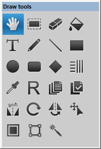
Figure 5.1 Toobar icons
Toolbar is in the left of software, it provides the basic and common tools use in paiting, which contains move, select, eraser, fill, text, pencil and so on. Following contents will show you how to use them.
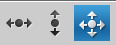
5.1 Move
Not selected

Selected

Choose: Click the icon of “Move” in toolbar with left mouse button, the icon vides supra. When the icon is selected, the background color will turn to mazarine.
5.2 Select
Not selected

Selected

Choose: Click the icon of “Select” in toolbar with left mouse button, the icon vides supra. When the icon is selected, the background color will turn to mazarine.
Operation: Choose an rectangle area in workspace, you can drag the area you selected, also you can copy it for pasting next time, see figure 5.1.
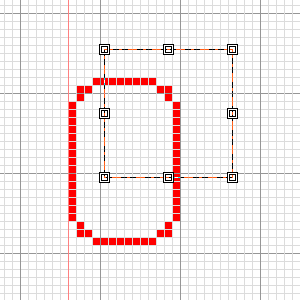
Figure 5.1 Operation of select
5.3 Eraser ممحاة
Not selected

Selected

Choose: Click the icon of “Eraser” in toolbar with left mouse button, the icon vides supra. When the icon is selected, the background color will turn to mazarine.
Operation: Move the cursor to the position where you need in workspace, long-press left mouse button and drag it, then the area’s pattern will be erased.
Setting: You can set the size of eraser. Click the icon for setting line widths, then select an item in pull-down menu, see figure 5.2.
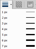
Figure 5.2 Setting of eraser size
5.4 Fill ملء اللون
Not selected

Selected

Three modes of fill: normal fill, clipboard contents fill and shape fill.
Choose: Click the icon of “Fill” in toolbar with left mouse button, the icon vides supra. When the icon is selected, the background color will turn to mazarine.
Operations
① Normal fill: Choose a color in Color Bar, then you select an area in workspace, click the mouse, the area will be filled with the color you selected, see figure 5.3. If you don’t select any area, the color will fill the whole area except some closed areas.
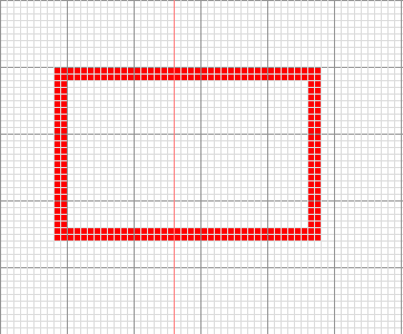

Figure 5.3 Normal fill
(Left: A rectangle. Right: The filled rectangle)
② Clipboard contents fill: If you have some contents in your clipboard, when you select this mode, the area will be filled with your contens in clipboard, figure 5.4 shows the clipboard’s content is an angle of a rectangle. The related operations are same as normal fill’s operations.
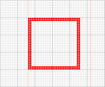
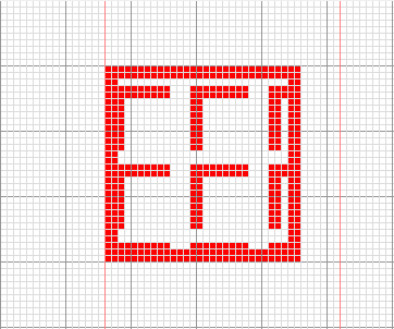
Figure 5.4 Clipboard contents fill
(Left: A rectangle. Right: The rectangle filled with clipboard’s contents)
③ Shape fill: Choose the icon in “Draw Settings” toolbar, select a mode, see figure 5.5. If there is no mode, you can see the contents in “6.5 Pattern Edit”. In figure 5.6, the area will be filled with the shape in the mode.The related operations are same as normal fill’s operations.

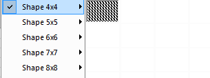
Figure 5.5 Choose the mode of shape
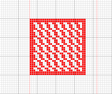
Figure 5.6 Shape fill
(Left: A rectangle. Right: The rectangle is filled with a shape)
5.5 Text كتابة كلمة او شعار
Not selected

Selected

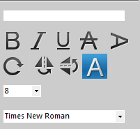
Options of text
Choose: Click the icon of “Text” in toolbar with left mouse button, the icon vides supra. When the icon is selected, the background color will turn to mazarine.
The options
Click the text field to activate it, this is used to input the text.

Bold. Click this option to select it, again to cancel selection. When selected, the text will be be turn to bold.

Italic. Click this option to select it, again to cancel selection. When selected, the text will be be turn to italic.

Underline. Click this option to select it, again to cancel selection. When selected, there has line under the text.

Strickout. Click this option to select it, again to cancel selection. When selected, there has line through the text.

Vertical. Click this option to select it, again to cancel selection. When selected, the text displays in vertical.

Rotate random. Click this option to select it, again to cancel selection. When selected, you can adjust the text’s angle through the cursor.

Flip horizontally. Click this option to select it, if you want to cancel the selection, you should click “Flip vertically” or “No flip”. When selected, you can adjust the text to let it flip in a horizontal direction.

Flip vertically. Click this option to select it, if you want to cancel the selection, you should click “Flip horizontally” or “No flip”. When selected, you can adjust the text to let it flip in a vertical direction.

No flip. Click this option to select it, if you want to cancel the selection, you should click “Flip horizontally” or “Flip vertically”. When selected, the horizontal filp and vertical flip are all canceled.

Set the size of text. You can choose a number in pull-down menu.

Set the font of text. You can choose a font in pull-down menu.
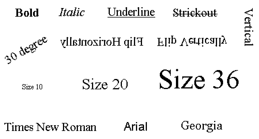
Figure 5.7 The diffrent effects of text
Operation: Input the text in text field, choose some options with the mouse, the move the cursor to workspace, choose a position and click the left mouse button to finish it.
Setting: You can set the color of text through color bar.
5.6 Pencil
Not selected

Selected
Choose: Click the icon of “Pencil” in toolbar with left mouse button, the icon vides supra. When the icon is selected, the background color will turn to mazarine.
Operation: Move the cursor to the position where you need in workspace, long-press left mouse button and drag it, then you can draw the pattern with pencil, when you finish it, releases left mouse button.
Setting: You can set the size of pencil. Click the icon for setting line widths, then select an item in pull-down menu. You can also set the color through color bar.

5.7 Line
Not selected

Selected

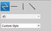
Options: From left to right in row one, there are Normal Line, Horizontal Line, Vertical Line and Angle Line. Row two is the angles you can set in “Angle Line” mode. Row three is custom style.
Choose: Click the icon of “Line” in toolbar with left mouse button, the icon vides supra. When the icon is selected, the background color will turn to mazarine.
Operation: Move the cursor to the position where you need in workspace, long-press left mouse button and drag it, then you can draw the line you want, when you finish it, releases left mouse button.
Setting: You can set the size of pencil. Click the icon for setting line widths, then select an item in pull-down menu. You can also set the color through color bar.
5.8 Rectangle
Not selected

Selected

Choose: Click the icon of “Rectangle” in toolbar with left mouse button, the icon vides supra. When the icon is selected, the background color will turn to mazarine.
Operation: Move the cursor to the position where you need in workspace, long-press left mouse button and drag it, then you can draw the rectangle you want, when you finish it, releases left mouse button.
Setting: You can set the size of pencil. Click the icon for setting line widths, then select an item in pull-down menu. You can also set the color through color bar.
5.9 Oval
Not selected

Selected

Choose: Click the icon of “Oval” in toolbar with left mouse button, the icon vides supra. When the icon is selected, the background color will turn to mazarine.
Operation: Move the cursor to the position where you need in workspace, long-press left mouse button and drag it, then you can draw the oval you want, when you finish it, releases left mouse button.
Setting: You can set the size of pencil. Click the icon for setting line widths, then select an item in pull-down menu. You can also set the color through color bar.
5.10 Rounded rectangle
Not selected

Selected

Choose: Click the icon of “Rounded rectangle” in toolbar with left mouse button, the icon vides supra. When the icon is selected, the background color will turn to mazarine.
Operation: Move the cursor to the position where you need in workspace, long-press left mouse button and drag it, then you can draw the rounded rectangle you want, when you finish it, releases left mouse button.
Setting: You can set the size of pencil. Click the icon for setting line widths, then select an item in pull-down menu. You can also set the color through color bar.
5.11 Diamond
Not selected

Selected

Choose: Click the icon of “Diamond” in toolbar with left mouse button, the icon vides supra. When the icon is selected, the background color will turn to mazarine.
Operation: Move the cursor to the position where you need in workspace, long-press left mouse button and drag it, then you can draw the diamond you want, when you finish it, releases left mouse button.
Setting: You can set the size of pencil. Click the icon for setting line widths, then select an item in pull-down menu. You can also set the color through color bar.
5.12 Insert/Delete
Not selected

Selected

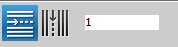
Options: From left to right in row one, there are insert/delete line, insert/delete row, text field
Choose: Click the icon of “Insert/Delete” in toolbar with left mouse button, the icon vides supra. When the icon is selected, the background color will turn to mazarine.
Operation
① Set the number of line or row: Click the text field, input a number.
② Insert/Delete line: Click the icon of insert/delete line, then move the cursor to workspace, click left mouse button to insert the line, click right mouse button to delete the line.
③ Insert/Delete row: Click the icon of insert/delete row, then move the cursor to workspace, click left mouse button to insert the row, click right mouse button to delete the row.
Original Insert 10 lines Delete 10 lines Original Insert 10 rows Delete 10 rows
Figure 5.8 Different effects of insert/delete
5.13 Color Picker
Not selected

Selected

Choose: Click the icon of “Color Picker” in toolbar with left mouse button, the icon vides supra. When the icon is selected, the background color will turn to mazarine.
Operation: Move the cursor to workspace, choose a color you need, move the cursor upon the color area, then click the left mouse button to pick color. Color Picker can use with fill color.
5.14 Rubber
Not selected

Selected

Options: From left to right in row one, there are mesh shape, bars, mosaic and ratio choose.
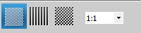
Choose: Click the icon of “Rubber” in toolbar with left mouse button, the icon vides supra. When the icon is selected, the background color will turn to mazarine.
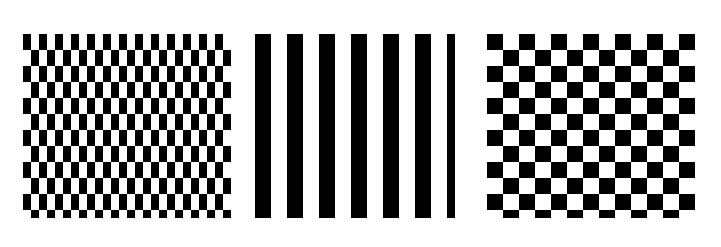
2:2 Mesh shape 2:2 Bars 2:2 Mosaic
Figure 5.9 Three modes of rubber
Operation
① Choose a ratio: You can choose a ratio in pull-down menu in right.
② Draw a rubber: Move the cursor to workspace, press the left mouse button in long-time and drag it, when you finish it, release the button.
5.15 Repeated Copy
Not selected

Selected

Choose: Click the icon of “Repeated Copy” in toolbar with left mouse button, the icon vides supra. When the icon is selected, the background color will turn to mazarine.
Operation: Move the cursor to workspace, press the left mouse button in long-time and drag it, when you finish it, release the button. Then the area you copy will move with the cursor, choose the position you need, click the left mouse button again to finish pasting. You can repeat this action many times. Press right mouse button to exit the pasting.
5.16 Selection Copy
Not selected

Selected

Options: Left is Linear Painting. Right is Array Painting.

Choose: Click the icon of “Selection Copy” in toolbar with left mouse button, the icon vides supra. When the icon is selected, the background color will turn to mazarine.
Operation: Move the cursor to workspace, press the left mouse button in long-time to select the the pattern you need, then choose “Linear Painting” or “Array Painting”. At last, move the cursor to workspace again, press the left mouse button in long-time and drag it to paint the pattern you want. Figure 5.10 shows the different effects of linear painting and array painting.

Figure 5.10 Different effects of linear painting and array painting
5.17 Mirror
Not selected

Selected

Options: Left is “L/R Mirror”, right is “Symmetrical Mirror”. In L/R Mirror mode, the left half of workspace’s pattern will be copy to the right half. In Symmetrical Mirror mode, the left half of workspace’s pattern will be flipped in horizontal, then copy to the right half.

Choose: Click the icon of “Mirror” in toolbar with left mouse button, the icon vides supra. When the icon is selected, the background color will turn to mazarine.
Operation: When you finish painting, choose one option, the pattern will be turn to the mode you selected. Figure 5.11 shows the difference of these two modes.
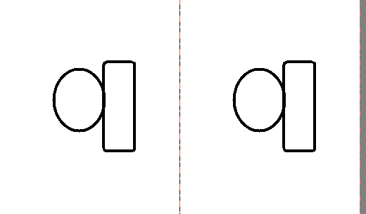

Figure 5.11 L/R Mirror and Symmetrical Mirror
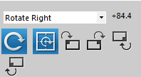
5.18 Rotate
Not selected

Selected

Options: Line one is choose a rotate angle. Line two to line three, from left to right, there are Rotate random, Rotation around the center, Rotation around upper left, Rotation around upper right, Rotation around lower right, Rotation around lower left.
Options explaination
Choose a rotate angle: Choose a angle in pull-down menu.
Rotate random: Rotate the pattern a random angle through the cursor.
Rotation around the center: Rotate the pattern around the pattern’s center.
Rotation around upper left: Rotate the pattern around the pattern’s upper left.
Rotation around upper right: Rotate the pattern around the pattern’s upper right.
Rotation around lower right: Rotate the pattern around the pattern’s lower right.
Rotation around lower left: Rotate the pattern around the pattern’s lower left.
Choose: Click the icon of “Rotate” in toolbar with left mouse button, the icon vides supra. When the icon is selected, the background color will turn to mazarine.
Operation
① Rotate in fixed angle
Click icon in options, then the icon will turn to gray(not selected). Choose one rotate mode, then move the cursor to workspace, select an area you need. At last, choose an fixed angle in pull-down menu to finish the rotating.


② Rotate manually
Click icon in options, then then icon will turn to mazarine(selected). Choose one rotate mode, then move the cursor to workspace, select an area you need. Release the left mouse button, move the cursor, the area will rotate with the cursor, click the left mouse button in the angle you want.
5.19 Flip
Not selected

Selected

Options: From left to right, there are Horizontal Flip, Vertical Flip and No Flip.

Options explaination
Horizontal Flip: Flip the pattern you select in horizontal direction.
Vertical Flip: Flip the pattern you select in vertical direction.
No Flip: Not flip the pattern you select.
Choose: Click the icon of “Flip” in toolbar with left mouse button, the icon vides supra. When the icon is selected, the background color will turn to mazarine.
Operation: Choose one flip mode you need, then move the cursor to workspace, press the left mouse button in long-time to select an area you want. After selection, release the left mouse button, the area will flip as you wish, press “Enter” to finish the operation while “Esc” to cancel it. Figure 5.12 shows the different effects of horizontal flip and vertical flip.
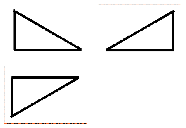
Figure 5.12 Flip effects
5.20 Roll
Not selected

Selected

Options: From left to right, there are L/R Roll, Up/Down Roll and Random Roll.
Options explaination
L/R Roll: Roll the pattern in horizontal direction.
Up/Down Roll: Roll the pattern in vertical direction.
Random Roll: Roll the pattern in random direction.
Choose: Click the icon of “Roll” in toolbar with left mouse button, the icon vides supra. When the icon is selected, the background color will turn to mazarine.
Operation: Choose one option, then move the cursor to workspace, press the left mouse button in long-time to select an area you need. Release the left mouse button, the area you selected has a frame. Move the cursor to the area, click the left mouse button again in long-time to drag it. At last, release the left mouse button at the position you want.
5.21 Frame
Not selected

Selected

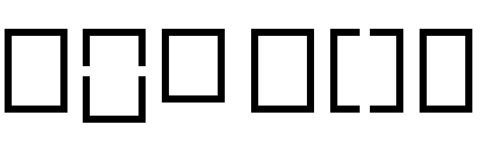
Options: From left to right, there are full border, top border, bottom border, left border and right border.
Options explaination
Full Border: Draw a region’s border.
Top Border: Draw a region’s top border.
Bottom Border: Draw a region’s bottom border.
Left Border: Draw a region’s left border.
Right Border: Draw a region’s right border.
Operation: Choose one option and choose a color in color bar, then move the cursor to workspace, click the left mouse button in a region, the operation is finished.
5.22 Cutout
Not selected

Selected

Choose: Click the icon of “Cutout” in toolbar with left mouse button, the icon vides supra. When the icon is selected, the background color will turn to mazarine.
Operation: Move the cursor to workspace, press the left mouse button in long-time to start cutout. The cutout need a closed area, if you don’t cut a closed area, the system will close the area automatically. After cutout, drag the area you cut, move it to the position you need, double-click the left mouse button to finish it.
5.23 Magic Wand
Not selected

Selected

Choose: Click the icon of “Magic Wand” in toolbar with left mouse button, the icon vides supra. When the icon is selected, the background color will turn to mazarine.
Operation: Move the cursor to workspace, click the left mouse button in somewhere you need, then the magic wand will search the same color as you just clicked, and close the area automatically. After that, drag the closed area, move it to the position you need, double-click the left mouse button to finish it.
6 Menu Bar
The Menu Bar has a clear and hierarchical structure, it provides the user different common operations and parameter settings.
6.1 File
The shortcut key for choosing menu “File” is “Alt” + “F”. There are 14 items under menu “File”, see figure 6.1. These items are all relate to the file operations.
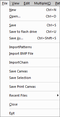
Figure 6.1 The file menu
Create a new file
When you choose “New” in menu “File”, you can create a new file, shortcut key is “Ctrl” + “N”. After you choosing it, there will be a dialog to set width and height for the new file, see figure 6.2. Default value is 144 by 400. The width range is 30 to 512, while the height range is 1 to 65535, see figure 2.2 and figure 2.3.

Figure 6.2 Set width and height for file

Figure 6.3 The range of width

Figure 6.4 The range of height
Open a file
When you choose “Open” in menu “File”, you can open a file in your disks, shortcut key is “Ctrl” + “O”. After you choosing it, there will be a dialog to open a file, see figure 6.5.
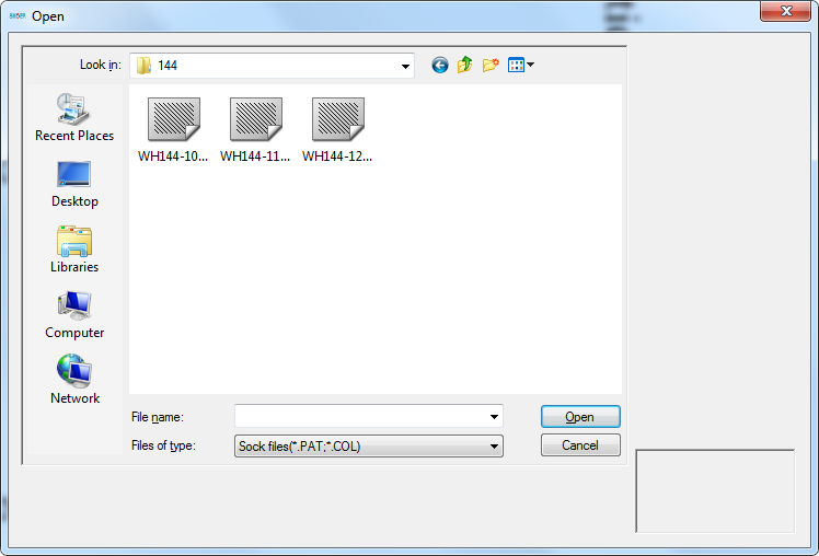
Figure 6.5 The dialog for opening a file
Save the file
When you choose “Save” in menu “File”, you can save the file after you editing the pattern file, shortcut key is “Ctrl” + “S”. After you choosing it, there will be a dialog to choose a position for saving, you can name it and choose a saving position, see figure 6.6.
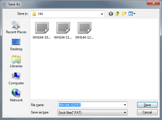
Figure 6.6 Save the file
Save file to flash drive
When you choose “Save to flash drive” in menu “File”, you can save the file to flash drive after you editing the pattern file, shortcut key is “Ctrl” + “U”. After you choosing it, the file will save to your flash drive automatically, see figure 6.7. When you are not connecting your flash drive to PC, the system will give you a warning.
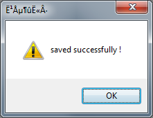
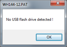
Save complete No flash drive
Figure 6.7 Save the file to flash drive
Save file as other format
When you choose “Save as” in menu “File”, you can save the file as other format to your disk, shortcut key is “Ctrl” + “Shift” + “S”. After you choosing it, there will be a dialog to save the file. You can name the file, choose a format to save and select a position in your disk, see figure 6.8.
Figure 6.8 Save file as other format dialog
Import patterns
When you choose “Import patterns” in menu “File”, you can import a pattern to your file. After you choosing it, there will be a dialog to select patterns, see figure 6.9. The patterns format include “.daq” and “.dap”.

Figure 6.9 Import patterns
Import BMP file
When you choose “Import BMP File” in menu “File”, you can import a picture to your file. After you choosing it, there will be a dialog to select the picture. The pictures format include “.bmp”, “.jpg”, “.tif”, “.png”, “.gif” and so on.
The dialog for selecting picture is shown in figure 6.10, you can also set picture’s height and width in this dialog.
After you choosing the picture, there will be a dialog to transform color, see figure 6.11. You can choose a color in the options under “Substitute”.
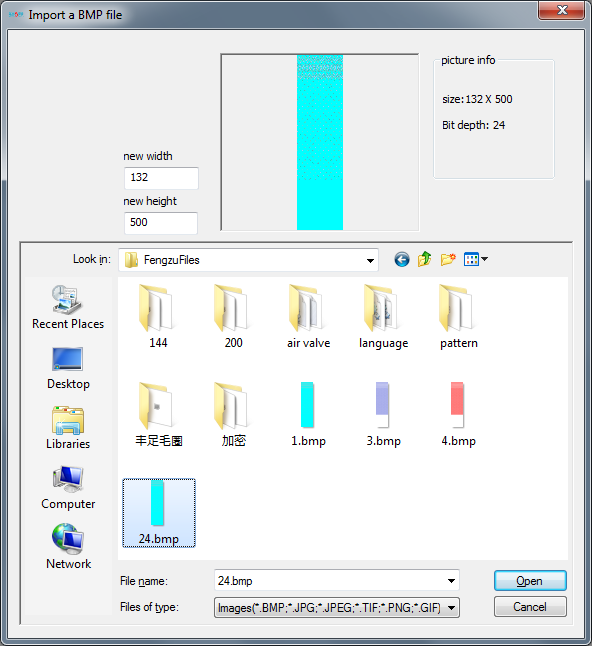
Figure 6.10 Import the picture

Figure 6.11 Color transform
Import chain
When you choose “Import Chain” in menu “File”, you can import a chain to your file. After you choosing it, there will be a dialog to select the chain, see figure 6.12. The chain’s format is “.cam”.
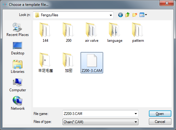
Figure 6.12 Import the chain
Save Canvas
When you choose “Save Canvas” in menu “File”, you can export your file editing as a BMP file. After you choosing it, there will be a dialog to select the position, see figure 6.13.
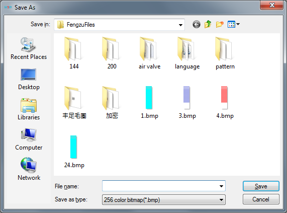
Figure 6.13 Save canvas
When you choose “Save Selection” in menu “File”, you can save the area you selected as a BMP file. After you choosing it, there will be a dialog to select the position, see figure 6.14.
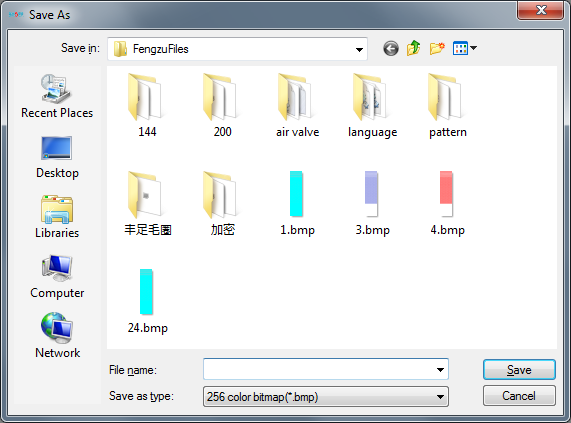
Figure 6.14 Save selection
Save Print Canvas
When you choose “Save Print Canvas” in menu “File”, you can save a canvas in you computer for printing, see figure 6.15.

Figure 6.15 Save print canvas
Recent Files
There is a list of in “Recent Files” in “File” menu, this list is the recently opened files list, which you recently edit. You can click to open it directly.
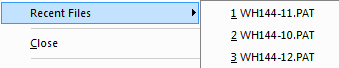
Figure 6.16 Recent files list
Close
When you choose “Close” in menu “File”, you can close the pattern you are editing, then the window will turn to gray.
Exit
When you choose “Exit” in menu “File”, the whole software will be closed.
6.2 View
The shortcut key for choosing menu “View” is “Alt” + “V”. “View” menu contains the common icons used in drawing patterns. Same kind of icons will form a tool bar. You can choose the tool bar if you want it display in the main interface. When there is a “√” in front of the words, that means the tool bar you selected will be displayed in the main interface, see figure 6.17.
Toolbar
The submenu of “Toolbar” in menu “View” is formed with three parts, which are common toolbars, detail informations and customize. You can select the items except customise item. When the items are selected, there will be a “√” in front of the items. Select again, the “√” will disappear, the items will disappear in the main interface too.
① Common toolbars
This part are formed with “Common toolbar”, “Draw Settings”, “CAT toolbar” and “Map Views”. See figure 6.17, they are the ones marked with “√” in submenu “Toolbar”. Their usages are described in section “7 Toolbar under menu”
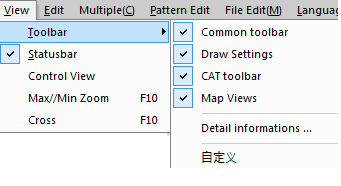
Figure 6.17 Structure of “Toolbar”
② Detail informations
When you choose “deteail informations” in submenu “Toolbar”, there will be a dialog showing in the workspace, it contains the information about location, pattern, main shuttle, rubber and so on. See figure 6.18.

Figure 6.18 Detail informations
③ Customize
The last part in “Toolbar” is customize. The dialog is showing in figure 6.19.

Figure 6.19 The dialog of customize
In this dialog, you can define menu bar, tool bar, shortcut key, style of menu and item setting.
Statusbar
Statusbar is the second item in menu “View”. It locates in bottom of the software, which shows the basic information about the pattern file, see figure 6.20. When you choose it, you can see a “√” in front of the word, statusbar will display in the software.

Figure 6.20 Statusbar
Control View
Control View is the third item in menu “View”. When you choose it, you can see a “√” in front of the words, there will be a scrollbar in right side of the software. When you pull the scrollbar, it will help you see different part of the pattern file. If you don’t choose “Control View”, there is not a scrollbar in right side of the software.
Max/Min Zoom
Max/Min Zoon is the fourth item in menu “View”. When you click it, the workspace will change between maximum and minimum. You can also operate it with button “F10”.
Cross
Cross is the last item in menu “View”. When you choose it, you can see a “√” in front of the word. At that time, there are two cross lines around the cursor. If you don’t choose it, there will be no cross lines. See figure 6.21, left part show the cross lines while the other part has no cross lines.
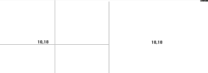
Figure 6.21 Cross lines and no cross lines
The shortcut key for choosing menu “Edit” is “Alt” + “E”. This menu provides you seven kinds of common operation about editing file, see figure 6.22.
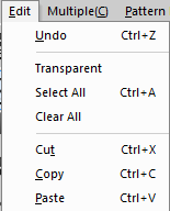
Figure 6.22 The menu of “Edit”
Table 6.1 describes functions of the items in menu “Edit”.
Table 6.1 Functions of items in menu “Edit”
No. | Submenu | Shortcut key | Functions | Remarks |
1 | Undo | Ctrl + Z | Cancel the current operation, return to previous operation | |
2 | Transparent | - | Set background picture transparent | |
3 | Select all | Ctrl + A | Select all parts of the pattern file be editing | |
4 | Clear all | - | Clear all the content of pattern file be editing | |
5 | Cut | Ctrl + X | Cut the content has been selected | |
6 | Copy | Ctrl + C | Copy the content has been selected | |
7 | Paste | Ctrl + V | Paste the content has been copied or cut |
6.4 Multiple
Multiple view contains a couple of common views, see figure 6.23. When you choose it, the item will display in bottom of the painting area. Choose the item to turn to this view. The items in this menu are same as “Map View” toolbar.
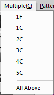
Figure 6.23 The menu of “Multiple”
Table 6.2 describes functions of the items in menu “Multiple”.
Table 6.2 Functions of items in menu “Multiple”
No. | Submenu | Shortcut key | Functions | Remarks |
1 | 1F | Add 1F view to bottom of the software | ||
2 | 1C | - | Add 1C view to bottom of the software | |
3 | 2C | - | Add 2C view to bottom of the software | |
4 | 3C | - | Add 3C view to bottom of the software | |
5 | 4C | - | Add 4C view to bottom of the software | |
6 | 5C | - | Add 5C view to bottom of the software | |
7 | All visible | - | Add all views to bottom of the software |
6.5 Pattern Edit
The shortcut key for choosing menu “Pattern Edit” is “Alt” + “E”, you can set and edit some attributes of pattern files, and also you can set the parameters related to the attributes, see figure6.24
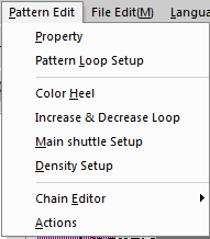
Figure 6.24 The menu of “Pattern Edit”
Property
The function of “Property” in menu “Pattern Edit” is resizing the pattern file, you can see a dialog through “Pattern Edit” – “Property”, see figure 6.25.

Figure 6.25 Resizing the pattern file
You can input height and width of the pattern file in this dialog. The range of height is 1 to 65535, and width is 30 to 512. You can also choose “Scale” when you adjust size.
Pattern Loop Setup
Pattern loop setup is used to set loop’s start, end and circle’s value. You can see the setup dialog through “Pattern Edit” – “Pattern Loop Setup”, see figure 6.26.
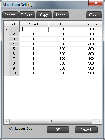
Figure 6.26 Pattern loop setup
The functions of the buttons in this dialog will be described in following content.
Insert: Insert a line of null.
Delete: Delete current line.
Copy: Copy current line’s data.
Paste: Paste the data has been copied to current line.
Clear: Clear all the data in loop.
Ok: Save the data.
Cancel: Cancel the operation.
Color Heel
Color heel is used to set main-yard, in, out and rows’ value. It also set the start value for each plan. You can see the setup dialog through “Pattern Edit” – “Color Heel”, see figure 6.27.

Figure 6.27 Color heel setup
Choose editable item in the dialog, input the value and click “OK” to save the result. “Clear All” is used to clear the data you set. If you want to cancel the operation, choose “Cancel”.
Increase & Decrease Loop
Increasing and decreasing loop is used to set the value of increasing and decreasing in both left and right way. You can see the setup dialog through “Pattern Edit” – “Increasing & Decreasing Loop”, see figure 6.28.

Figure 6.28 Increase & decrease loop setup
Choose editable item in the dialog, input the value and click “OK” to save the result. “Clear All” is used to clear the data you set. If you want to cancel the operation, choose “Cancel”.
Main Shuttle Setup

Figure 6.29 Main shuttle setup
Main shuttle setup is used to choose different shuttles with different id, set the values of “advanced” and “overlap”. You can see the setup dialog through “Pattern Edit” – “Main Shuttle Setup”, see figure 6.29.
Choose main shuttles of every line in the dialog, and set the values of “advanced” and “overlap”. Click “OK” to save the reasult, click “Cancel” to cancel the operation.
Density Setup
Density setup is used to set the value of parameters in CYL density and raising CAM density. You can see the setup dialog through “Pattern” – “Density Setup”, see figure 6.30.
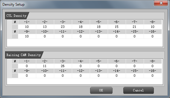
Figure 6.30 Density setup
Choose editable item in the dialog, input the value and click “OK” to save the result. If you want to cancel the operation, choose “Cancel”.
Chain Editor
Chain edit contains “Basic Edit” and “Advanced Edit”. You can see the submenu through “Pattern Edit” - “Chain Editor”, see figure 6.31.
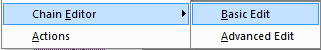
Figure 6.31 Chain Editor
① Basic Edit
The dialog for basic edit is shown in figure 6.32. If you want to setuo the parameters in this dialog, you need to click button “Advanced” in the bottom of the dialog and input authorization password, see figure 6.33.
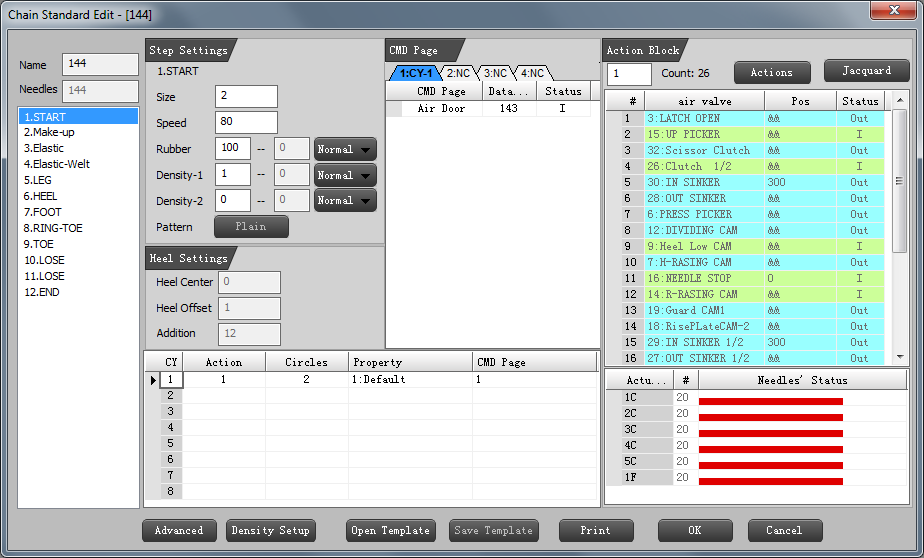
Figure 6.32 The dialog for basic edit
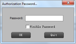
6.33 Input the authorization password
After input the password, you can edit the chain in this interface.
Action Edit
Buttons’fuction
Density Setup: Set the data for density.
Open Template: Load a chain file.
Save Template: Save the chain file as a template.
Print: Save the data to a txt file.
OK: Save the result.
Cancel: Cancel the operations.
Edit the parameters
Step Settings: The parameters in area “A” see figure 6.32.
Heel Settings: The parameters in area “B” see figure 6.32.
CY: Edit the parameters in area “C”, see figure 6.32.
CMD Settings: The parameters in area “D” see figure 6.32.
Action Settings: The parameters in area “E” see figure 6.32. (In section ”Action” )
Jacquard Settings: The parameters in area “F” see figure 6.32. (In section “Action”)
② Advanced Edit
Before enter the dialog of advanced edit, you should input he authorization password, see figure 6.34. Then you will enter the interface of advanced edit, you can edit the chain in this dialog, and also manage the actions, edit the jaquards. At last, click “OK” to save the result.
Figure 6.34 Input the authorization password
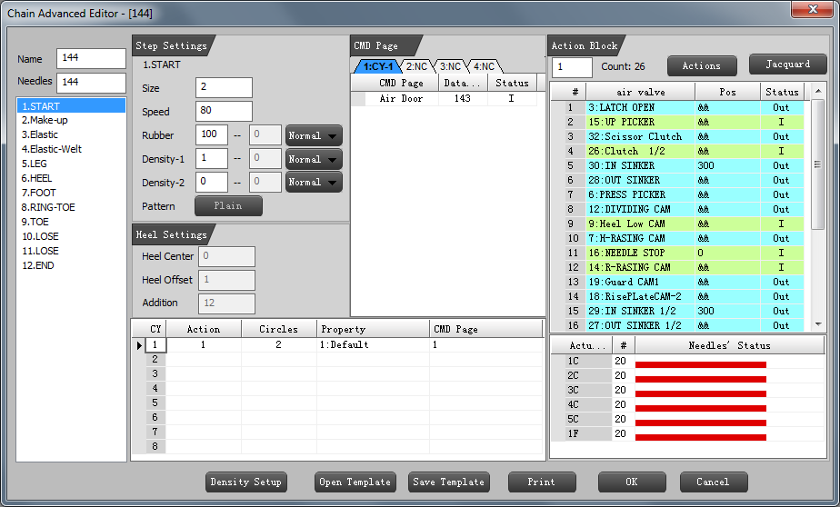
Figure 6.35 The dialog for advanced edit
Actions
Action manager dialog is used to manage actions and edit jacquards. Choose “Actions” in menu “Pattern Edit”, click button “Advanced”, input authorization password, see figure 6.36.
Figure 6.36 Input the authorization password
You can enter another dialog after you input the password, see figure 6.37. Button “Advanced” has been gray.
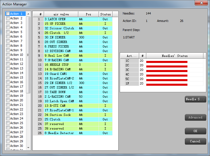
Figure 6.37 The dialog of action manager
Choose an action in the list of left side in figure 6.37, click the right mouse button, the menu likes figure 6.38.
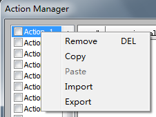
Figure 6.38 Edit of actions
The edit of actions contains following parts.
Delete: Delete the action’s data you select.
Copy: Copy the action’s data you select.
Paste: Paste data you copy to the action you select.
Import: Import an action file (extensions with “.tsa”)
Export: Export select action to an action file.
Click the right mouse button in the blank area of the interface, then there will be a menu, see figure 6.39. Because there is no line in the region, so only “Insert” in menu is useful.
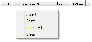
Figure 6.39 Edit the field
In figure 6.39, choose “Insert”, and then you can insert a new line, see figure 6.40. You can choose an air value, set a value of position (range is 0 to 720) and choose a status with “Out” or “in”.
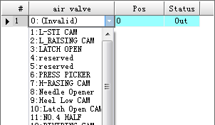
Figure 6.40 Insert a new line
After you insert a new line, you can select the line and clickthe right mouse button, then there will be a menu like figure 6.41.
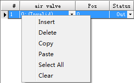
Figure 6.41 Editing the new line
The functions of the items in this menu will be decried in following section.
Insert: Insert a new line.
Delete: Delete the current line.
Copy: Copy the current line.
Paste: Paste the line you have copied to current line.
Select All: Select all the lines.
Clear: Delete all the lines.
Click button “Needle Setup” in action manage interface to enter needle setup dialog, see figure 6.42.

Figure 6.42 Needle setup dialog
There are twenty jacquards in the list. Choose one of them, and blue part in top of dialog is showing the every needle’s status. Click one of the needles, the needle’s status will change to “out”, while the default status is “in”. The number top of the needle status is current needle’s serial number, see figure 6.43.
The status will change after click it Current needle’s serial number

Figure 6.43 Editing the needle’s status
There are two groups of buttons in left of the dialog: Modify and Unitary. These two groups of buttons are used to edit the jacquards, there will be the paraphrases for each button in following section.
Buttons in “Modify” contains: Repeated copy and Local copy.
Repeated copy: Copy the status which is between serial number A and B (A < B), repeat this part of status after location B until the end of needles.
Figure 6.44 shows the needle’ s status result through the operation “Repeated copy” in figure 6.43.

Figure 6.44 Repeated copy
At last, click button “OK” to save the result, see figure 2.44, which shows the status of jacquard.

Figure 6.45 The status of jacquard after “Repeated copy”
Local copy: Copy the status which is between serial number A and B (A < B), repeat this part of status between C and D (C<D) after location B.
Figure 6.46 shows one jacquard’ s initial status. We will copy the status between needle 1 and needle 5, and then repeat this part’s status to needle 11 to needle 15 through button “Local copy”. The steps are described in figure 6.47.

Figure 6.46 Jacquard’s initial status
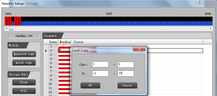
Figure 6.47 Local copy
At last, click button “Ok” to save the result, see figure 6.48, which shows the status of jacquard.

Figure 6.48 The status of jacquard after “Local copy”
Buttons in “Unitary” contains: Clear, Fill, Copy and Paste.
Clear: Set all needles’ status default, which is “in”.
Fill: Set all needles’ status “out”.
Copy: Copy all the needles’ status in current jacquard.
Paste: Paste the status has copied to the current jacquard.
There are two same buttons in both needles setup dialog and action manage interface: “OK” and “Cancel”. “OK” is used to save the result, while “Cancel” is used to cancel the operation.
6.6 File Edit
The shortcut key for choosing “File Edit” is “Alt” + “T”. There is only one submenu in “File Edit”, which is “MAC File”, this item can edit the parameters related to machine, elastic, air valve and so on.
MAC File
Before you enter the dialog for machine file editing, you should input authorization password, see figure 6.49.
Figure 6.49 Input the anthorization password
After you input the password, there will be a dialog for editing machine file, see figure 6.50.

Figure 6.50 Machine file editing dialog
There are three items in top of the dialog: Open, Save and Save as.
Open: Open an effective machine file(extension is” .mac” ) to import the parameters, if the file is not effective, there will be a warning, see figure 6.51.

Figure 6.51 The file you import is not effective
Save: Save the setting as a machine file.
Save as: Save the setting as other format files.
Machine file setup is formed with four parts: Machine setup, Elastic setup, Air valve setup and Reset chain.
Machine setup part is like figure 6.52 shows. In this part, you can set the parameters of machine, selector and “T position”. You can input the value in text boxes and select an item in pull-down menu.
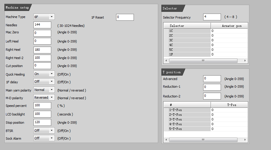
Figure 6.52 Machine parameters setup
Elastic setup
Elastic setup part is like figure 6.53 shows. In this part, you can set the parameters of two elastic when the elastic’s status is “in” or “out”. You can input the value in text boxes.
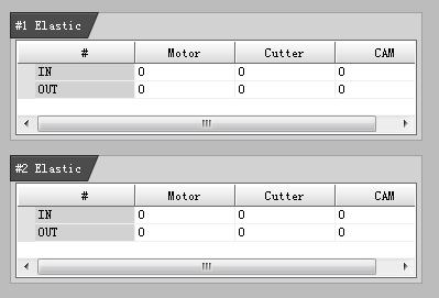
Figure 6.53 Elastic setup
Air valve setup part is like figure 6.54 shows. In this part, you can set the parameters of plating air valve, terry air valve, shuttle air valve and reset air valve. You can select an item in pull-down menu.

Figure 6.54 Air valve setup
Reset chain
Reset chain setup part is like figure 6.55 shows. In this part, you can set the parameters of step, create a new command, manage the actions and edit the jacquards.
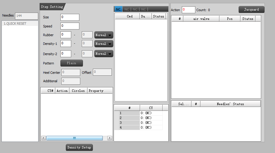
Figure 6.55 Reset chain
Step setting
Top half of the step parameters in dialog can input in text boxes or select an item through pull-down menu. In the bottom half of the dialog, you can insert a new line through mouse the right key. After you insert a new line, you can edit it, see figure 6.56.
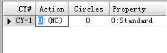
Figure 6.56 Step setting
Create a new command
In middle region of reset chain part, first you should input the value of “CY”, then you can insert a command in top of the region through click the right mouse button, see figure 6.57.
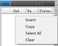
Figure 6.57 Create a new command
Edit the command, set parameters related to the command to finish the task.
Manage the actions
In right top blank region of reset chain part, you can insert an action through the right mouse button, see figure 6.58. About editing and management for actions, you can see the content in section 6.5.

Figure 6.58 Manage the actions
Click button “Jacquard” to enter jacquards editing dialog. About editing the jacquards, you can see the content in section 6.5.
6.7 Languages
The shortcut key for choosing menu “Languages” is “Alt” + “L”. There are five languages in this menu: Chinese(Simplified), English, Turkish, Russian and Arab, When you choose one of them, the system language will change to the language what you choose. The menu is shown in figure 6.59.
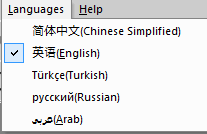
Figure 6.59 Languages menu
6.8 Help
This menu provides the user matters need attention in the menual. You can also see the version information from this menu.
Help Topics
“Help Topics” provides user the instruction and help information, if you need some help, you can click the menu.
Version
“Version” provide user the software version and company information, see figure 6.60.
Figure 6.60 Version information
7 Toolbar under menu
Toolbar under menu is a group of icons, which have similar functions. This is easy for editing and operation.
The common toolbars contains “Common toolbar”, “Draw Settings”, “CAT toolbar” and “Map Views”, these toolbars correspond with first four items in submenu “Toolbar” of menu “View”, when you choose them, the toolbar will display in the software.
7.1 Common toolbar
Common toolbar locates at top left, which has tools for common use when you editing a pattern file, see figure 7.1. You can also drag the toolbar with mouse to anywhere in workspace.

Table 7.1 describes the functions of tools in “Common toolbar”.
Table 7.1 The function of tools in “Common toolbar”
No. | Icons | Name | Shortcut key | Function | Remarks |
1 | New | Ctrl + N | Create a new file | ||
2 | Open | Ctrl + O | Open an existing file | ||
3 | Save | Ctrl + S | Save the file | ||
4 | Save to flash drive | Ctrl + U | Save the file to flash drive | ||
5 | Backup | - | Keep a backup of the file | ||
6 | Cut | Ctrl + X | Cut the content user selected | ||
7 | Copy | Ctrl + C | Copy the content user selected | ||
8 | Paste | Ctrl + V | Paste the content user cut or copy | ||
9 | Undo | Ctrl + Z | Undo the operation, return to previous operation | ||
10 | Redo | Ctrl + Y | Redo the operation been cancelled | ||
11 | Zoom in | Num + | Zoom in the editing region | ||
12 | Zoom out | Num - | Zoom out the editing region | ||
13 | Gridlines | - | Display or hide the gridlines: display when you press it, hide when you second press | ||
14 | About | - | Show the version, copyright, company information and so on | ||
15 | Help | Shift + F1 | Open the document for help |


7.2 Draw Settings
The draw settings toolbar is shown in figure 7.2. The tools in this toolbar are used to setting of some function related to drawing pattern. You can also drag the toolbar with mouse to anywhere in workspace.

Figure 7.2 Draw Settings
Table 7.2 describes functions of tools in “Draw Settings” toolbar.
Table 7.2 The functions of tools in “Draw Settings” toolbar
No. | Icons | Name | Shortcut key | Functions | Remarks |
1 | Choose lines | - | Choose different lines for drawing | ||
2 | Picture transparent | - | Set the picture loaded transparent | ||
3 | Fill with shape | - | Fill the shape you selected with a template | ||
4 | Edit shapes | - | Edit shapes in template | ||
5 | Multiple yarn setting | - | Needle thread repeatedly | ||
6 | Replace Color | - | Replace a color with another one | ||
7 | Exchange Color | - | Exchange two colors designated |


7.3 CAT toolbar
There are two tools in CAT toolbar, one is used to import a template file, and the other is used to edit the template. See figure 7.3. You can also drag the toolbar with mouse to anywhere in workspace.
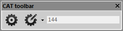
Figure 7.3 CAT toolbar
Table 7.3 describes functions of tools in CAT toolbar.
Table 7.3 The functions of tools in CAT toolbar
No. | Icons | Name | Functions | Remarks |
1 | Import a template file | Import a template file for drawing | ||
2 | Chain basic edit | Edit the chain in basic |


7.4 Map Views
There are twelve tools in “Map Views” toolbar, preceding nine of them are nine different views of pattern, and last three of them are assistant ones, see figure 7.4. You can also drag the toolbar with mouse to anywhere in workspace.
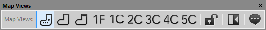
Figure 7.4 Map views
Table 7.4 describes functions of tools in View toolbar.
Table 7.4 The functions of tools in View toolbar
No. | Icons | Name | Functions | Remarks |
1 | Draw current action to pattern view | |||
2 | Main shuttle view | Draw current action to main shuttle view | ||
3 | Elastic view | Draw current action to elastic view | ||
4 | 1F View | Draw current action to 1F view | ||
5 | Draw current action to 1C view | |||
6 | 2C View | Draw current action to 1C view | ||
7 | 3C View | Draw current action to 1C view | ||
8 | 4C View | Draw current action to 1C view | ||
9 | 5C View | Draw current action to 1C view | ||
10 | Lock status | The actions will drawn to the current view when the status is lock, or only the next action will drawn to the current view | ||
11 | Toggle Control View | Show or hide the toggle | ||
12 | Cursor information | Show the information about the cursor position |


8 Color Bar
The color bar provides you different colors. You can choose one of them as foreground color or background color. When you choose the different view, the color related to the view will be different. Figure 8.1 to figure 8.4 lists four different color bars related to the four different views.
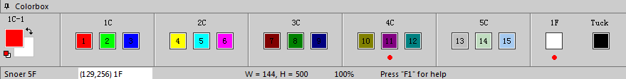
Figure 8.1 Color bar related to pattern view
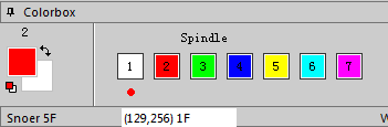
Figure 8.2 Color bar related to main shuttle view
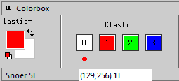
Figure 8.3 Color bar related to elastic view

Figure 8.4 Color bar related to 1F view
There are only two colors in 1C view to 5C view, same with 1F view.
How to choose a color as foreground color or background color:
1. Click the color-block with the left mouse button, it will be the foreground color.
2. Click the color-block with the right mouse button, it will be the background color.
9 Workspace
The center of workspace is painting area, there are two hiding windows in the right, which are merged views and chain standard edit.
9.1 Merged views
When your cursor hover the “Merged views”, the dialog will open, see figure 9.1.
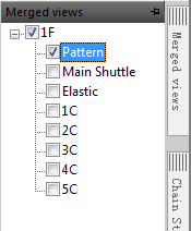
Figure 9.1 Meged views
The function of merged views is merging the pattern view with any other views. Choose “Pattern” first, then choose another view, you can see the effect in painting area.
9.2 Chain Standard Edit
When your cursor hover the “Chain Standard Edit”, the dialog will open, see figure 9.2.
Chain standard edit is used to edit the chain’s parameters, the operation is same with the related content in “6.5 Pattern Edit”.
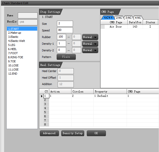
Figure 9.2 Chain Standard Edit
10 Context Menu
When you click the right mouse button in workspace, there will pop-up a menu, that is context menu. Context menu takes great convenience to the user.
The context menu is shown in figure 10.1, you can click any one of them to use it. Most functions of these items are described in above. There will be a table with brief description, see table 10.1.
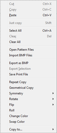
Figure 10.1 Context Menu
Table 10.1 Brief description about context
No. | Name | Shortcut key | Description | Remarks |
1 | Cut | Ctrl + X | Cut the content has been selected | |
2 | Copy | Ctrl + C | Copy the content has been selected | |
3 | Paste | Ctrl + V | Paste the content has been copied or cut | |
4 | Just copy | Shift | Open or forbid copy operation | |
5 | Select All | Ctrl + A | Choose all pattern in painting area | |
6 | Clear | Del | Delete the pattern in selection | |
7 | Clear all | - | Clear all pattern in painting area | |
8 | Open Pattern Files | - | Open a pattern file in the folder | |
9 | Import BMP Files | - | Import a BMP file in the folder | |
10 | Export as BMP | - | Export the pattern as BMP format | |
11 | Export Selection | - | Export the selection pattern | |
12 | Save Print File | - | Save the selection as a document | |
13 | Repeat Copy | - | Copy the selection repeatedly | |
14 | Geometrical Copy | - | Copy the selection, use it to liner painting or array painting | |
15 | Symmetry | - | Copy the painting area’left half or its mirror, paste it to right half | |
16 | Rotate | - | Change the angle of selection | |
17 | Flip | - | Flip the selection in horizontal or vertical | |
18 | Roll | - | Move the pattern in selection area | |
19 | Change Color | - | Change one color in selection | |
20 | Swap Color | - | Swap two colors in selection | |
21 | Copy to | - | Copy the current view’s pattern to another view |
See figure 10.2, when you want to change one color in selection, you should designate the original color and the substitute color.

Figure 10.2 Change color
See figure 10.3, when you want to swap two colors in selection, you should designate the original color and the substitute color.
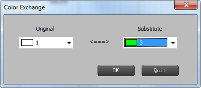
Figure 10.3 Swap color
See figure 10.4, when you want to copy the current view’s pattern to another view, you should designate the original color and the substitute color fo two views.

Figure 10.4 Copy current view’s pattern to another view
11 Hotkeys
To make a great convenient for user, the software provides a lot of hotkeys, see table 11.1.
Hotkeys | Function | Remarks |
F1 | Open help manual | |
F2 | Open chain edit dialog | |
F3 | Change current view | |
F9 | Show/Hide the cross lines | |
F10 | Maximum/Minimu show the painting area | |
F11 | Zoom - | |
F12 | Zoom + | |
Alt + F | Open “File” menu | |
Alt + V | Open “View” menu | |
Alt + E | Open “Edit” menu | |
Alt + C | Open “Multiple” menu | |
Alt + P | Open “Pattern Edit” menu | |
Alt + M | Open “File Edit” menu | |
Alt + L | Open “Languages” menu | |
Alt + H | Open “Help” menu | |
Ctrl + N | Create a new file | |
Ctrl + O | Open a file | |
Ctrl + S | Save a file | |
Ctrl + U | Save the file to flash disk | |
Ctrl + Shift + S | Save the file as | |
Ctrl + Z | Undo the last operation | |
Ctrl + A | Select the whole pattern in in painting area | |
Ctrl + X | Cut the selection | |
Ctrl + C | Copy the selection | |
Ctrl + V | Paste the pattern you have copied | |
Del | Delete the pattern you have selected |
تعليقات
إرسال تعليق